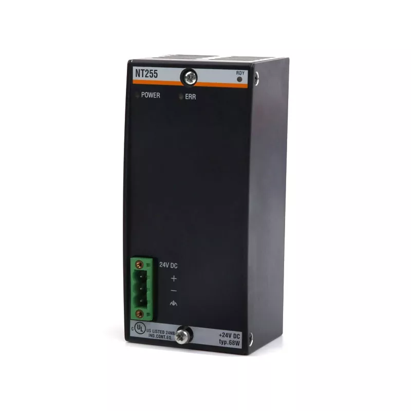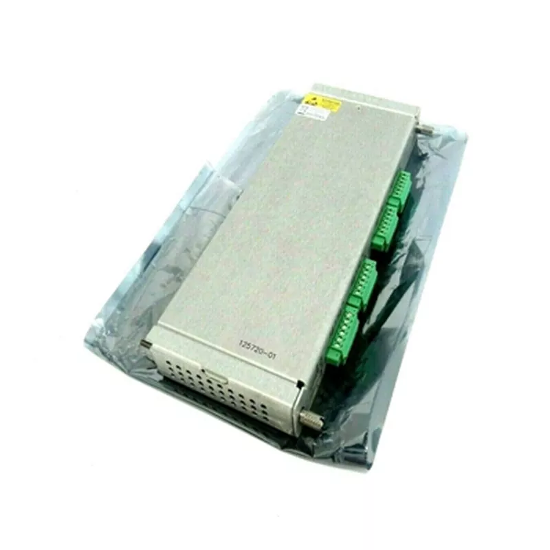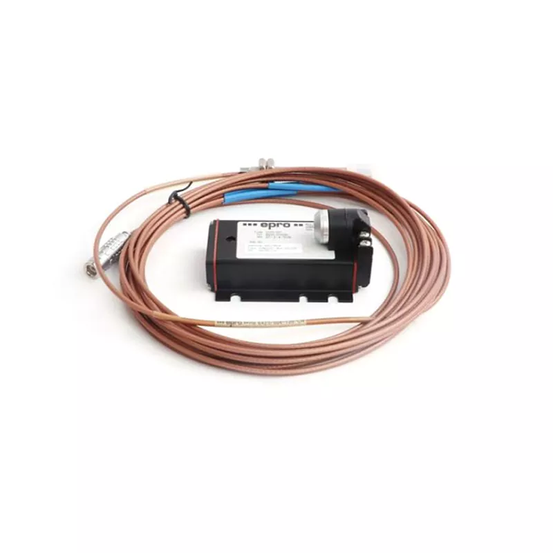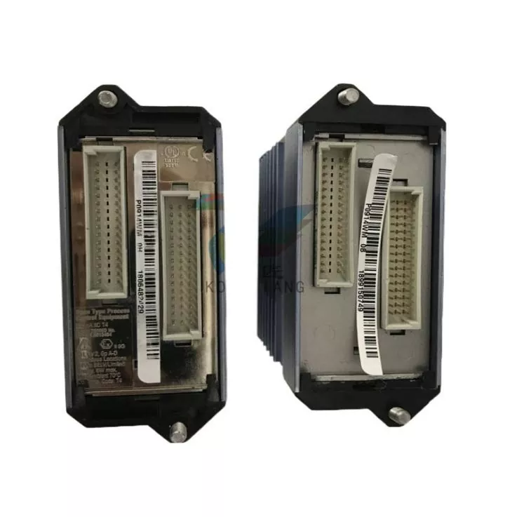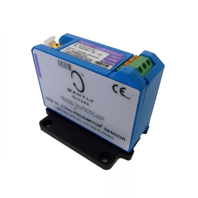
A Bently Nevada 3500 Machinery Protection System is designed to monitor the operating condition of critical rotating equipment, identify abnormal mechanical behaviour, and initiate protective responses when measured parameters exceed configured limits. By collecting signals from proximity probes, seismic transducers, temperature sensors, speed sensors, and other field instruments, the system gives plant personnel a structured view of machinery health. Its principal functions include vibration monitoring, shaft position measurement, speed monitoring, alarm management, relay-based protection, and communication with plant-level control and diagnostic platforms.
In industrial environments where a turbine, compressor, pump, motor, or generator is essential to production, an undetected mechanical fault can lead to equipment damage, unplanned shutdowns, safety concerns, and significant maintenance costs. The 3500 platform addresses these risks through a modular rack architecture that can be configured around the measurement requirements of individual machines. For buyers searching for Bently Nevada PLC equipment, it is important to understand that the 3500 is primarily a machinery protection and condition monitoring platform rather than a conventional programmable logic controller. Its monitoring modules process machine measurements, while configured relay outputs can connect protection decisions to suitable shutdown or annunciation circuits.
1. What Machinery Protection Functions Does the 3500 System Perform?
2. Which Modules and Technical Parameters Determine System Capability?
3. How Should Plants Configure, Integrate, and Maintain the System?
The main purpose of a machinery protection platform is not simply to display operating values. It must acquire dependable signals, interpret those signals against engineering limits, identify abnormal conditions, and make the resulting information available to operators and maintenance teams. The 3500 platform combines these tasks in one rack-based system. Its functions can be adapted to different machine types by selecting suitable monitor modules, transducers, I/O arrangements, alarm settings, and relay logic.
Vibration is one of the most useful indicators of rotating machinery condition. Changes in vibration amplitude, frequency, phase, or waveform can be associated with mechanical problems such as rotor imbalance, shaft misalignment, looseness, bearing deterioration, rubbing, and changes in operating conditions. The 3500 system accepts signals from compatible proximity probes and seismic transducers, allowing engineers to select measurements that match the machine construction and diagnostic objective.
For machines fitted with proximity probes, radial shaft vibration measurements can help identify changes in the movement of the rotor relative to the bearing or probe mounting position. Seismic transducers, including velocity sensors and accelerometers, provide information about casing or structural vibration. These measurement methods are complementary rather than interchangeable. The appropriate sensor depends on the machine design, bearing arrangement, shaft accessibility, operating speed, and applicable monitoring specification.
The 3500/40M Proximitor Monitor and 3500/42M Proximitor/Seismic Monitor are two important examples. The 3500/40M supports functions such as radial vibration, thrust position, eccentricity, and differential expansion. The 3500/42M expands the available measurement choices to include acceleration, velocity, shaft absolute, and circular acceptance region monitoring, subject to channel configuration. Both modules use conditioned transducer signals and configurable alarm setpoints to help identify abnormal conditions.
For maintenance teams, the value of continuous vibration monitoring lies in the ability to observe trends instead of relying only on occasional inspections. A gradual increase in vibration may indicate a developing problem before it becomes severe enough to cause a forced outage. Engineers can compare measurements with historical operating data, review changes after maintenance, and investigate whether an abnormal reading is associated with load, speed, temperature, or another operating variable. However, vibration data should always be interpreted in the context of machine design and operating conditions. A single high reading does not automatically identify a specific fault.
Rotating machinery depends on controlled mechanical clearances. Axial movement, radial displacement, shaft eccentricity, and thermal expansion can affect the relationship between rotating and stationary components. If these movements exceed the limits established for a particular machine, the result may be increased wear, internal rubbing, bearing damage, or other mechanical consequences.
The 3500 platform supports several measurements relevant to these conditions:
The 3500/45 Position Monitor is designed for position-related applications including axial position, differential expansion, ramp differential expansion, case expansion, and valve position. The 3500/40M and 3500/42M also support selected position measurements. Selection should be based on the required measurement type rather than on a module number alone. For example, a machine requiring a specific ramp differential expansion arrangement may need a different configuration from one requiring only standard differential expansion monitoring.
In a steam turbine, axial position and differential expansion can be particularly important because the rotor and casing may experience different thermal growth during start-up, loading, and shutdown. In a compressor, shaft vibration and thrust position can provide useful information about rotor behaviour and bearing performance. The engineering team must define the measurement points, probe locations, scaling factors, alarm limits, and trip logic using the machine manufacturer's requirements and the applicable protection standard.
Vibration readings are more useful when they can be assessed alongside other operating variables. Rotor speed, bearing temperature, process pressure, flow, and load can all influence machine behaviour. The 3500 platform therefore supports more than vibration measurements alone.
The 3500/50M Tachometer Module can monitor rotor speed, rotor acceleration, zero speed, and reverse rotation, depending on its configuration. Speed information can be used for operational monitoring, alarm generation, and correlation with vibration behaviour. It can also provide reference information for tracking measurements. It is important to observe the manufacturer's application limitations: the 3500/50M is not intended to serve as an overspeed protection system. A dedicated emergency shutdown or overspeed protection solution should be selected where that function is required.
Temperature monitoring is available through modules such as the 3500/60, 3500/61, and 3500/65. The 3500/60 and 3500/61 provide six-channel temperature monitoring functions, while the 3500/65 provides a 16-channel option. Temperature information can help operators evaluate bearing conditions, winding temperatures, and other monitored points when suitable sensors and input arrangements are installed.
For process-related measurements, the 3500/62 Process Variable Monitor accepts proportional inputs such as 4 to 20 mA and supported voltage signals. These inputs can represent variables including pressure, flow, level, motor current, or other process measurements. The 3500/64M Dynamic Pressure Monitor is intended for dynamic pressure applications, including the monitoring of combustion pressure pulsations in gas turbines. These functions allow machine measurements to be considered alongside relevant process conditions.
Monitoring becomes machinery protection when configured limits and response logic are connected to the plant's operating and shutdown philosophy. The 3500 system supports digitally adjustable Alert and Danger setpoints. Alert levels can indicate that a monitored value has moved outside its normal operating range, while Danger levels can identify conditions requiring a more urgent response. Depending on configuration, alarms can be set to latch or operate without latching.
The 3500/32M Relay Module provides four relay channels, while the 3500/33 provides 16 relay channels. These modules can be configured to respond to alarm conditions from monitor modules in the rack. Relay logic can use individual channel status, Alert or Danger conditions, and combinations of conditions. AND and OR logic, voting arrangements, and latching options can be applied where supported by the configuration.
For example, a plant may configure a relay to respond only when two relevant measurement channels reach a defined alarm state. Another arrangement may use separate relay outputs for different machine sections or alarm categories. This flexibility allows the protection design to reflect the machine's risk assessment and shutdown requirements rather than forcing every installation into one fixed logic arrangement.
Correct engineering is essential. The rack's general Rack OK relay is intended for annunciation of rack or module health and should not be treated as a machinery automatic shutdown output. For suitable shutdown applications, the designated relay modules and their engineered alarm drive logic should be used. The complete trip circuit must also be reviewed as a system, including field wiring, external logic, final elements, power supplies, proof testing, and the relevant safety requirements.
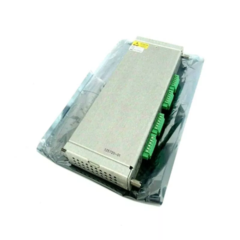
The 3500 system is modular. A typical installation combines an instrument rack, power supply modules, a Transient Data Interface module, monitor modules, corresponding I/O modules, and any required relay, communication, or display modules. The configuration is selected according to the number of measurement points, machine types, required protection functions, integration requirements, and site installation conditions. This is why buyers should confirm the complete part number and configuration instead of purchasing a monitor module based only on a short product description.
The 3500/05 Instrument Rack provides the physical platform for the system. The standard rack is available in 19-inch EIA rail-mount, panel-cutout-mount, and bulkhead-mount versions. Two power supply positions and the TDI position are reserved at the left side of the standard rack. The remaining 14 slots can accommodate compatible monitor, relay, Keyphasor, display, and communication gateway modules.
A 12-inch mini rack is also available. It provides seven available monitor slots, with the power supply and TDI positions reserved in the same general arrangement. This smaller rack can be useful where the number of measurement channels is limited or cabinet space is constrained. It is not simply a smaller enclosure: the available module capacity must be considered when planning future expansion.
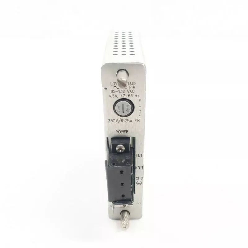
The 3500/15 Power Supply accepts AC or DC input versions, allowing the rack to be matched to different site power arrangements. A rack can operate with one supply, or two supplies can be installed for redundancy. Each supply can power the complete rack. In a dual-supply arrangement, the backup supply can take over if the primary supply fails, helping maintain rack operation. The final selection should account for the site's power quality, available sources, redundancy philosophy, and electrical installation requirements.
The 3500/22M Transient Data Interface, commonly called the TDI, provides the primary interface between the rack and configuration, display, and condition monitoring software. It supports rack configuration and communication with System 1 condition monitoring and diagnostic software. The TDI also provides rack-level status and configuration functions. It should not be confused with the monitor modules that perform the primary machine measurement and protection functions.
The following table summarises commonly specified module types and their principal roles. It is intended as a selection guide, not as a substitute for the current module datasheet or an approved system bill of materials.
| Module model | Channel capacity or arrangement | Main function | Typical application focus |
| 3500/15 | Power supply module | Provides rack power from AC or DC input versions | Rack power and optional redundant supply arrangement |
| 3500/22M | One TDI per rack | Rack interface, configuration access, and System 1 connectivity | System configuration and condition monitoring communication |
| 3500/25 | Supports up to two Keyphasor transducers per module | Provides phase reference signals for speed and related measurements | Rotating machinery speed and phase reference |
| 3500/40M | Four channels | Proximity monitoring for vibration and position measurements | Radial vibration, thrust position, eccentricity, and selected differential expansion functions |
| 3500/42M | Four programmable channels | Proximitor and seismic monitoring | Radial vibration, thrust position, acceleration, velocity, shaft absolute, and other supported measurements |
| 3500/45 | Four channels | Position monitoring | Axial position, differential expansion, case expansion, and valve position |
| 3500/50M | Two channels | Tachometer monitoring | Rotor speed, acceleration, zero speed, and reverse rotation |
| 3500/60 and 3500/61 | Six channels | Temperature and differential temperature monitoring | Bearing, winding, and other temperature measurement points |
| 3500/62 | Six channels | Process variable monitoring | Pressure, flow, level, current, and other proportional process signals |
| 3500/32M | Four relay channels | Configurable relay outputs | Alarm annunciation and engineered protective logic |
| 3500/33 | Sixteen relay channels | Higher-density relay output arrangement | Multiple alarm and relay logic requirements |
| 3500/92 | Communication gateway | Modbus communication over supported serial and Ethernet connections | Selected rack data exchange with plant systems |
Part numbers are only one part of a correct procurement specification. A monitor module may have several revisions, I/O options, termination arrangements, or configuration requirements. A replacement module must be compatible with the installed rack and the existing system configuration. Before placing an order, maintenance engineers and purchasing teams should verify the following technical information:
For procurement teams sourcing Bently Nevada PLC products, the distinction between a complete rack and an individual module is especially important. A 3500/42M monitor, for example, is not a complete machinery protection system by itself. It must be installed in a compatible rack and used with the correct I/O arrangement, power supply, TDI, transducers, configuration, and any required relay outputs. A missing or mismatched component can delay commissioning even when the monitor module itself is correct.
Unlike a single-purpose instrument with one fixed measurement range, the 3500 platform is configured around the selected monitor modules and field sensors. Its technical capability is therefore determined by the combined system architecture. The standard rack offers 14 module slots beyond the reserved power supply and TDI positions, while the mini rack offers seven available monitor slots. The system supports one or two power supplies, a required TDI, one or more monitor modules, and optional relay, Keyphasor, communication, display, and safety interface modules.
The 3500/42M provides four programmable channels, but the measurement functions are assigned in channel pairs. This means that channels 1 and 2 can be configured for one function while channels 3 and 4 perform another supported function or the same function. The 3500/32M provides four DPDT relay channels, while the 3500/33 provides 16 SPDT relay channels. These differences affect cabinet space, wiring, relay logic design, and the number of external circuits that can be controlled.
The 3500/92 gateway supports Modbus communication through serial and Ethernet protocols. The actual data points exchanged with a distributed control system or plant historian depend on the gateway configuration and the receiving system. Communication integration should therefore be checked at the signal and register level, not simply described as a general connection to any PLC or DCS.
When evaluating Bently Nevada PLC requirements, buyers should specify the intended outcome: continuous vibration measurement, shaft position protection, temperature monitoring, relay-based shutdown, process data integration, or diagnostic trending. Once the required functions are clear, the module selection becomes more accurate and the supplier can help check the part numbers against the installed configuration. Tongtu supports industrial buyers in identifying relevant Bently Nevada product models for maintenance, replacement, and project procurement. It recommends checking the full module and I/O combination before finalising a purchase. Yueyang Tongtu E-commerce Co., Ltd. can also review the requested model information to help reduce the risk of ordering an unsuitable component.
A machinery protection system delivers value only when its configuration reflects the real operating characteristics of the equipment it monitors. Installing a rack and connecting sensors is not enough. The engineering process must establish which failure modes matter, where measurements should be taken, what normal operating behaviour looks like, which alarm thresholds are appropriate, and how the plant should respond to each alarm state. A well-planned installation also considers commissioning, documentation, maintenance access, spare parts, and future changes to the machine or process.
The first step is to define the equipment being protected. A steam turbine, centrifugal compressor, boiler feed pump, generator, and reciprocating compressor have different mechanical characteristics and monitoring priorities. The protection design should begin with the machine data and relevant OEM recommendations rather than a generic module list.
For a large steam turbine, the monitoring plan may include shaft radial vibration, axial position, differential expansion, eccentricity, speed, and bearing temperature. A centrifugal compressor may require radial vibration, thrust position, speed, and process variables such as suction and discharge pressure. A reciprocating compressor may require rod position, rod drop, cylinder pressure, and vibration measurements suited to reciprocating motion. These requirements influence the choice of monitor modules and transducers.
A practical engineering review should document:
Alarm setpoints should not be copied from another machine simply because it has a similar model number. The appropriate limits depend on the machine design, measurement location, operating speed, sensor characteristics, OEM guidance, and applicable standards. Where a machine has multiple operating states, the engineering team may also need to account for start-up, shutdown, load changes, and transient conditions. A poorly selected alarm threshold can cause nuisance alarms or fail to identify a developing fault in time.
Once the measurement plan is approved, the rack can be configured using the 3500 System Configuration Software. The configuration includes channel names, alarm setpoints, signal processing options, communication parameters, and relay logic. Settings are stored through the TDI, and configuration access is controlled through the system's available security features.
Alarm design should distinguish between information intended for operator awareness and conditions requiring a protective action. An Alert may prompt an operator to investigate a changing trend, inspect operating conditions, or schedule maintenance. A Danger condition may be assigned to a relay output that participates in a defined shutdown circuit. The exact response must follow the plant's protection philosophy and risk assessment.
Relay logic can combine multiple channel states where the design requires voting or conditional operation. For example, an engineered logic scheme may require more than one related measurement to reach a specified state before a relay changes condition. Such arrangements can help reduce the likelihood of an unnecessary trip caused by an isolated signal problem, but they must be designed and validated for the actual machine and safety requirements. Voting should never be added merely to reduce nuisance alarms without assessing the consequences of delaying a protective action.
The distinction between monitoring communication and protection outputs also matters. A gateway can transfer selected status and measurement information to a control system, historian, or plant computer. That communication path is useful for operational visibility and trending, but it should not automatically be treated as a substitute for engineered protection relays. The protection function must remain consistent with the system design and the required reliability level.
When connected to System 1 condition monitoring and diagnostic software, the 3500 rack can provide data for a more proactive machinery maintenance programme. Operators can review current machine condition, while vibration analysts and reliability engineers can investigate trends and diagnostic information. This creates a link between real-time protection and longer-term asset management.
For example, a maintenance team may compare vibration data before and after a bearing replacement. If the overall vibration level decreases but a particular frequency component remains elevated, engineers can investigate whether the original fault has been fully corrected. Similarly, a gradual change in shaft position or bearing temperature can be reviewed alongside load and process conditions. These comparisons help maintenance teams distinguish a persistent mechanical issue from a temporary change caused by operating conditions.
Useful practices include:
Trend information should support engineering judgement, not replace it. A vibration increase may be related to a mechanical fault, but it can also be influenced by operating speed, process load, sensor installation, cable condition, or configuration changes. Reliable diagnosis requires an understanding of the machine and the measurement chain. A good maintenance process therefore combines instrument data with inspection findings, operating logs, repair records, and specialist analysis.
Commissioning verifies that the installed hardware, field instruments, configuration, alarm logic, and external interfaces work as intended. It should be completed against approved drawings and test procedures. The objective is not merely to confirm that the rack powers up, but to demonstrate that each required measurement is valid and that the intended alarm and relay responses occur under the specified test conditions.
A commissioning and maintenance checklist may include the following activities:
Routine maintenance should also include inspection of connectors, terminal blocks, cable condition, cabinet cleanliness, ventilation, and environmental protection. In hazardous areas, the suitability and condition of barriers, isolators, and enclosures must be checked in accordance with the approved installation design. Any module replacement should be followed by the required configuration, compatibility, and functional checks. A replacement part that physically fits the rack is not necessarily a suitable substitute for the original part number or revision.
For buyers sourcing Bently Nevada PLC equipment, accurate identification before shipment can reduce installation delays and unnecessary returns. Tongtu works with industrial procurement requirements involving Bently Nevada monitoring and protection products. The company encourages buyers to provide the complete part number, module revision, I/O model, and application details when requesting a quotation. Yueyang Tongtu E-commerce Co., Ltd. can use this information to help review the requested configuration and identify the relevant product specification. Tongtu aims to make model confirmation and industrial spare-parts procurement more straightforward for maintenance teams and system integrators.
The 3500 platform performs several connected functions: continuous vibration and position monitoring, speed and temperature measurement, process variable monitoring, configurable alarm management, relay-based protective actions, and communication with condition monitoring and plant systems. Its modular rack architecture allows the system to be configured for different rotating machines, but the correct combination of monitor modules, I/O modules, sensors, power supplies, and relay outputs must be determined by the actual application.
When evaluating Bently Nevada PLC requirements, buyers should identify the required machinery protection functions first and then confirm the complete hardware configuration. A correctly specified system can support earlier fault identification, more consistent alarm handling, better maintenance decisions, and improved protection of critical assets. Contact Yueyang Tongtu E-commerce Co., Ltd. with your required model, part number, or application details to discuss suitable Bently Nevada products and request a quotation for your industrial project.
The system can be configured for a wide range of rotating and reciprocating machinery, including steam turbines, gas turbines, centrifugal compressors, reciprocating compressors, pumps, motors, and generators. The actual measurement coverage depends on the selected monitor modules, compatible transducers, and system configuration. Typical measurements include radial vibration, shaft position, thrust position, differential expansion, rotor speed, temperature, and selected process variables. Engineers should select the measurement functions according to the machine design and the manufacturer's protection requirements.
Both modules support four-channel monitoring using compatible proximity measurement inputs, but the 3500/42M offers a broader selection of programmable measurement functions. The 3500/40M supports functions such as radial vibration, thrust position, eccentricity, and standard differential expansion. The 3500/42M adds supported functions including acceleration, velocity, shaft absolute, and circular acceptance region monitoring. The correct choice depends on the required measurement types, channel configuration, output requirements, and the installed I/O arrangement. Buyers should check the applicable datasheet and system revision before ordering.
Yes, a properly engineered 3500 configuration can use compatible relay modules and configured alarm drive logic to initiate protective actions through an appropriate shutdown circuit. The 3500/32M provides four relay channels, while the 3500/33 provides 16 relay channels. The relay logic can respond to configured Alert, Danger, and channel status conditions, including supported combinations and voting arrangements. However, the complete shutdown function depends on the external trip circuit, final control elements, wiring, power supply, testing, and applicable safety design. The rack's general Rack OK relay should be used for annunciation rather than as a machinery automatic shutdown output.
Yes. The system can exchange selected monitoring data and status information with plant automation and information systems through supported communication interfaces. The 3500/92 gateway supports Modbus communication over serial and Ethernet connections, while other gateway options support specific integration requirements. The 3500/22M TDI provides the rack's interface to configuration and System 1 condition monitoring software. The available data points and communication mapping depend on the gateway model, configuration, and receiving platform. Communication integration should be checked against the plant's protocol, register mapping, and cybersecurity requirements.
Buyers should provide the complete module part number, hardware revision, associated I/O module number, rack type, slot location, and required measurement or communication function. For monitor modules, it is also useful to provide the transducer model, channel assignment, signal type, and application details. For relay or communication modules, confirm the required number of outputs, relay logic, protocol, and external interface. If the item is intended to replace an installed module, photographs of the nameplate and existing connections, together with the rack configuration record, can help the supplier review compatibility before quotation and shipment.